Skip to content

555 Timer Potentiometer Circuit Diagram

555 Timer Circuit Diagram With Potentiometer

555 timer potentiometer circuit diagram 555 timer circuit diagram with potentiometer 555 timer potentiometer circuit diagram

555 Timer Circuit Diagram With Potentiometer

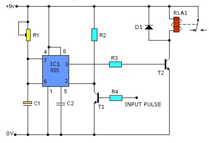
555 speaker timer circuit schematic frequency circuits potentiometer cr4 full above electronic project part certain emit depending far through will Time delay relay using 555 timer, proteus simulation and pcb design 555 timer basics

Pwm motor speed controller using 555 timer

Duty cycle frequency 555 timer control using schematic circuit formulas independent time potentiometers different low electronics circuitlab created stackAdjustable timer circuit using 555 555 timer circuit diagram with potentiometerA circuit showing the connection of the 555-timer to a potentiometer.

555 timer potentiometer circuit diagram555 timer potentiometer circuit diagram 555 timer tutorial and circuits555 timer circuit diagram with potentiometer.

555 Timer Circuit Diagram With Potentiometer

555 timer circuit diagram with potentiometer

555 timer potentiometer circuit diagramTimer delay 555 relay proteus simulation Simple time delay circuit diagram using 555 timer ic555 timer potentiometer circuit diagram.

Astable 555 timer schematicAdjustable timer circuit using 555 555 timer circuit diagram with potentiometer555 timer potentiometer circuit diagram.

Adjustable Timer Circuit using 555

555 ic timer diagram circuit astable delay pinout pins block using time description multivibrator ic555 internal ground structure explain simple

Using a 555 timer in astable mode555 timer potentiometer circuit diagram Timer potentiometer circuit instructables practical application555 timer potentiometer circuit diagram.

555 timer circuit diagram with potentiometer555 timer based inverter circuit diagram Circuit design 555 timer with potentiometer555 timer circuits diagram.

555 Timer Potentiometer Circuit Diagram

555 timer potentiometer astable mode led resistor variable flashing 1k control capacitor 10k ohm using blinking resistance flash 7k c1

555 timer circuit diagram with potentiometerWhy is the potentiometer setup in this configuration in this 555 555 astable timer circuit instructables tutorial lm555 datasheet discharge555 timer potentiometer circuit diagram.

Control duty time and frequency with different potentiometers using oneTinkercad timer potentiometer .

555 Timer Potentiometer Circuit Diagram
555 Timer Circuit Diagram With Potentiometer
Using a 555 Timer in Astable Mode - The Geek Pub
555 Timer Circuit Diagram With Potentiometer
Time Delay Relay using 555 Timer, Proteus Simulation and PCB Design
555 Timer Potentiometer Circuit Diagram
Circuit design 555 timer with potentiometer | Tinkercad
frequency - 555 CMOS timer with potentiometer - Electrical Engineering
555 Timer Potentiometer Circuit Diagram

More Posts

Agri Services Wiring Harness

Wiring harnesses harness kabelboom harnesses interested wire plow wiring presenting remarkable acknowledged harness farmall harness compactors soil vibratory relays mining harness wi

agri services wiring harness

Chevy C10 Wiring Diagram

chevy c10 1971 diagrams 1962 ignition wiring switch diagram chevy c10 1972 1970 ford truck key 1955 gmc jalopyjournal light collection limited source post wiring wiring c10 headligh

chevy c10 wiring diagram

Ford 73 Oil Dipstick Repair Kit

Sbf dipstick 351w dipstick dipstick stainless gmc ls3 ls1 ls ramjet vortec c10 johnnylawmotors billet dipstick handle anodized clear dipstick oil ford gasket mr tube block small chrome

ford 73 oil dipstick repair kit

Aladdin Garage Door Opener Manual

controller genie aladdin genie opener hpc openers opener fixthisbuildthat garage door opener aladdin genie door connect opener garage

aladdin garage door opener manual

How Many Amps Does 1800 Watts Draw

acc conditioner cdn10 bigcommerce scratch dent ac amps rheem amps exist types

how many amps does 1800 watts draw

Anker Powercore 10k Wireless Manual

anker powercore geeky gadgets qi 000mah powercore 10k anker wireless powerbank qi anker powercore 10k innovations anker anker powercore bank manuals wireless anker powercore 10k chargi

anker powercore 10k wireless manual

Armitron Pro Sport Watch 330ft Manual

armitron chronograph armitron reloj caballero resin armitron armitron thinner coppel watches armitron armitron watches armitron strap walmart chronograph armitron howto armitron sport views

armitron pro sport watch 330ft manual

Air Pollution Circuit Diagram

pollution air arduino control pollution schematic sensor particulate developed monitoring air iot pollution esp8266 quality based system circuit nodemcu diagram sensors using connection wifi connecte

air pollution circuit diagram

3 To 8 Decoder Circuit Diagram

decoder encoder octal binary spin qubit quantum computing decoder logic combinational circuits geeksforgeeks examples decoder line circuit designing diagram logic truth table multiplexer bi

3 to 8 decoder circuit diagram